Como comunicar com o CY8C9520A

Como comunicar com o CY8C9520A

Partilho neste artigo uma conversa por mail que tive com um seguidor, na sua dificuldade em como comunicar com o CY8C9520A, que é chip electrónico por vezes usado em certas aplicações práticas de modo a controlar ou a receber informação de algo.
Achei muito engraçado esta conversa, pois foi uma dificuldade grande que tive quando estava a desenvolver o meu projeto final da Faculdade, e por isso, decidi partilhar contigo este artigo.

Antes de continuar, fica aqui o convite para me enviares um mail, tal como faz este seguidor, caso tenhas um dúvidas na área da informática, Eletrónica, Investimentos, ou outra dúvida existencial 😀

Email

Olá Marcos,

O meu nome é *** e vi o seu vídeo no YouTube sobre o CY8C9520A. Eu próprio tenho o CY8C9560A.
Sou novo no CY8C9560A e queria saber se me podiam ajudar a aprender a comunicar com este chip em C++. Sei que é necessário comunicar com este chip via I2C, mas não consigo que ele leia os comandos. Teria algum código a explicar como fazer isso para que eu possa estudá-lo? Seria muito útil. Estou a trabalhar com um Arduino Nano e quero expandi-lo com este chip.

Adorava ouvir a sua opinião.

P.S.: Utilizei o Google Tradutor para traduzir este texto porque não falo português.
Atenciosamente,
******

Hi Marcos,

My name is ****, and I saw your video on YouTube about the CY8C9520A. I have the CY8C9560A myself.
I’m new to the CY8C9560A, and I was wondering if you could help me learn how to communicate with this chip in C++. I know you have to communicate with this chip via I2C, but I can’t get it to read the commands. Do you perhaps have any code for how you do it so I can study it? That would be very helpful. I’m working with an Arduino Nano, and I want to expand it with this chip.

I’d love to hear from you.

P.S. I ran this text through Google Translate because I don’t speak Portuguese.

Regards,
*****

A Minha resposta

Hello ****,

Hope this mail finds you well.
I can handle your english don’t worry 🙂.
First of all, thank you for your email, at least someone saw my strange youtube videos 😂.

And of course, i’m happy to share with you my experience with that chip. I work with that chip some years ago but i use Python in RaspberryPi and the library smbus2 (i2c) to control it.

First of all, you have to understand the chip. This chip has a lot of I/O ports and has a lot of functions like a watchdog, a timer, PWM and mainly the EEPROM (you can store the state of every I/O port at the “boot” of the chip like a BIOS PC for exemple). All of these functions (or whatever you want to call it) are divided in the chip by address in memory compartments that is called, in the datasheet by, Device Register Address. This table that you can find in the datasheet is very important when you’re studying the chip.

—— Traduzindo para Português ——

Olá, xxxxx,

Espero que este e-mail te encontre bem.
Não te preocupes, eu consigo lidar com o teu inglês 🙂.
Em primeiro lugar, obrigado pelo teu e-mail, pelo menos alguém viu os meus vídeos estranhos no YouTube 😂.

E, claro, fico feliz em partilhar contigo a minha experiência com esse chip. Trabalhei com esse chip há alguns anos atrás, mas usei Python no RaspberryPi e a biblioteca smbus2 (i2c) para controlá-lo.

Primeiro, é preciso entender o chip. Este chip tem muitas portas de E/S e muitas funções, como um watchdog, um temporizador, PWM e, principalmente, a EEPROM (é possível armazenar o estado de cada porta de E/S na «inicialização» do chip, como um BIOS de PC, por exemplo). Todas essas funções (ou como quiseres chamar) são divididas no chip por endereço em compartimentos de memória que são chamados, na ficha técnica, de Device Register Address (Endereço de Registro do Dispositivo). Essa tabela, que você pode encontrar na ficha técnica, é muito importante quando se estuda o chip.

For example, If you want to activate some ports (like turn on a LED) you will need to use the Output Port Registers that goes from 08hex to 0Fhex.

To communicate with the chip, i recommend you to use I2C, and i think is the only way. The Python library smbus2 can easily help you with that, however if you want to use C++ i can’t help you with that. If you have some library i2c that you can put what register you want to use, maybe you can control that chip directly with Arduino, otherwise i really don’t know.
Maybe if you try to connect Arduino by RS232 (Tx,Rx) with RaspberryPi you can make it. Sending data from Arduino, and the RaspberryPi receibes and activates the ports. Don’t know. Or else just try to find some library that you put what register you want to control.

I will send you down here some code that i use in the beginning and i think it could help you. Maybe you will need to you use ChatGPT or other LLM to translate Python to C++.

Look at the website of the library to know more of how to use the functions: https://smbus2.readthedocs.io/en/latest/ and Github: https://github.com/kplindegaard/smbus2

from smbus2 import SMBus
i2c = SMBus(1)
register=8 # is 8 because is the first register that controls the output ports of the chip, and you can verify in the table above from datasheet
i2c.write_i2c_block_data(address,register,[255]) #255 is a number base power of 2 (2^8) and in this case will turn on all outputs of the 8 register in other terms: will turn on 8 outputs
register=9
i2c.write_i2c_block_data(address,register,[255]) # will turn on the other 8 outputs of the 9 register. manipulating this power of 2 number you control which port to activate of this register

In this short example i just turn on all the output ports. If you put 0 in the last field you just turn off.
Related to the address: you need to find it first. In my youtube video that you saw, the project automatically searches the i2c address and “send” it for code that is running. Of course the code above is not the code of the video, but the mainly part is.

I hope that this explanation helped you.
If you need more help or more code don’t bother and send me an email. I will help you.

Best Regards,

—— Traduzindo para Português ——

Por exemplo, se quiseres ativar algumas portas (como ligar um LED), vais precisar de usar os Registros da Porta de Saída que vão de 08hex a 0Fhex.

Para comunicar com o chip, recomendo que uses o I2C, e acho até que é a única maneira. A biblioteca Python smbus2 pode ajudá-lo facilmente com isso, no entanto, se quiser usar C++, não te posso ajudar com isso. Se tiveres alguma biblioteca i2c na qual possas colocar o registo que desejas usar, talvez possas controlar esse chip diretamente com o Arduino, caso contrário, realmente não sei.
Talvez se tentares conectar o Arduino por RS232 (Tx, Rx) com o RaspberryPi, consigas fazer isso. Enviando dados do Arduino, o RaspberryPi recebe e ativa as portas. Não sei. Ou então, tenta encontrar alguma biblioteca na qual possas colocar o registo que desejas controlar.

Vou-te enviar aqui um código que usei no início e acho que te pode ajudar. Talvez precises usar o ChatGPT ou outro LLM para traduzir Python para C++.

Consulta o site da biblioteca para saber mais sobre como usar as funções: https://smbus2.readthedocs.io/en/latest/   e Github: https://github.com/kplindegaard/smbus2

from smbus2 import SMBus
i2c = SMBus(1)
register=8 # é 8 porque é o primeiro registo que controla as portas de saída do chip, e pode verificar na tabela acima da ficha técnica
i2c.write_i2c_block_data(address,register,[255]) #255 é um número de potência de base 2 (2^8) e, neste caso, ativará todas as saídas do registo 8. Em outras palavras: ativará 8 saídas
register=9
i2c.write_i2c_block_data(address,register,[255]) # ativará as outras 8 saídas do registo 9. Ao manipular esta potência do número 2, controla qual porta ativar deste registo

Neste breve exemplo, apenas ativei todas as portas de saída. Se colocar 0 no último campo, apenas desativará.
Em relação ao endereço: primeiro, é necessário encontrá-lo. No meu vídeo do YouTube que viu, o projeto procura automaticamente o endereço i2c e «envia-o» para o código que está a ser executado. É claro que o código acima não é o código do vídeo, mas a parte principal é.

Espero que esta explicação te tenha ajudado.
Se precisares de mais ajuda ou mais código, não hesites em enviar-me um e-mail. Eu ajudar-te-ei.

Cumprimentos,

Email

Good morning Marcos,

I appreciate you replying, because that doesn’t happen often.
Do you happen to still have the code you used in this video? I’m really curious about it.
(abaixo o video que a pessoa visualizou)
I have a friend who’s quite handy with Python, and he could probably help me convert it to C++.
I was looking at your site last night, and you teach PCB design.
That’s good to know, because I’m also working on that myself via Easy EDA, which I really enjoy.
I’m even making a few PCBs for a lab power supply I designed myself, and also for an 8-bit computer, and much more.
I’m not very good at programming yet, but I think I’ll get there through trial and error. I use Chatgpt a lot.

Sincerely,
xxxxxx

–Traduzindo para Português —

Bom dia Marcos,

Agradeço a sua resposta, porque isso não acontece com frequência.
Por acaso ainda tem o código que usou neste vídeo? Estou muito curioso sobre ele.
(abaixo o vídeo que a pessoa visualizou)
Tenho um amigo que é bastante habilidoso com Python e provavelmente poderia ajudar-me a convertê-lo para C++.
Estava a ver o seu site ontem à noite e vi que ensina design de PCB.
É bom saber, porque também estou a trabalhar nisso através do Easy EDA, que gosto muito.
Estou até a fazer alguns PCBs para uma fonte de alimentação de laboratório que eu mesmo projetei, e também para um computador de 8 bits, entre outras coisas.
Ainda não sou muito bom em programação, mas acho que vou chegar lá através de tentativa e erro. Uso muito o Chatgpt.

Atenciosamente,
xxxxxx

Minha Resposta

Hello xxxx,

What you saw in that video was the final project that i’ve done for my degree in Electrical Engineering. In that particularly video i was programing the EEPROM of the Chip with specific initial configurations needed were that PCB going to work.
The project consists basically in doing a basic electrical and communication test with several and different PCBs that my factory uses in different machines of production lines.
For each PCB i wrote a different code.
The most of those PCB’s use i2c communication. In this video you can see a bigger picture https://youtu.be/hWANM_KGzI0

I’ve done all the hardware and software(Python), in a timeframe where ChatGPT were not available 🙂. I used the PyQT5 framework (i learn from the book of this kind gentleman: https://www.martinfitzpatrick.com) for User Interface and then i’ve done a different program for each PCB.

For this specific PCB that you saw in the video, i send you in attach the main files that i think that can help you.

  • funcoes.py is the file where i wrote standard functions that i can call i several different PCB files. In that file the functions: read_i2c_address, deteta_endereco, deteta_endereco_ajuda are the mainly ones related to i2c address automatic detection (the file i2cdetect_exe is the one that scan i2c network and is kind a batch file that i run before all of this functions)
  • Easy2Repair.py is the main file of the program. Where i create the class of the whole project. In here i import the smbus2 library important for i2c communication. And i think it’s the only thing important from this file.
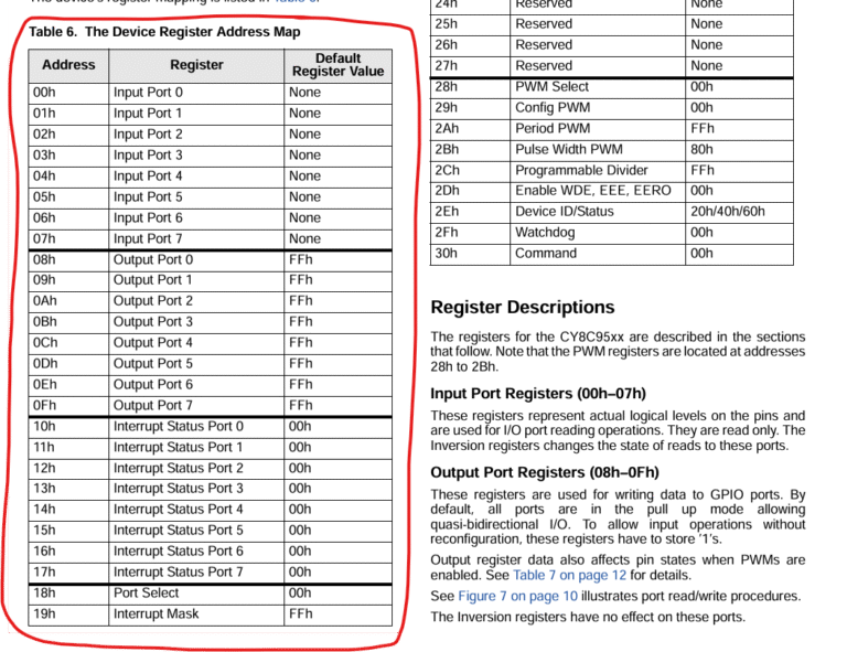
  • Universal_Meas_Mux.py is the file with specific code for the PCB that uses 2 chips CY8C9520A. The mainly thing to control the CY8C95 chips is this function (provide by the library smbus2) write_i2c_block_data, like i show you last email. In this PCB i program the EEPROM by enable it first, then i wrote to it and then i close communication however after that it must be power off and power on to continue the test. I think that procedure you won’t need it. This was a specific thing for our industrial machines in the place i work. However for enable EEPROM: i2c.write_i2c_block_data(self.endereco,45,[67,77,83,2]) , disable EEPROM is: i2c.write_i2c_block_data(self.endereco,45,[67,77,83,0]), save configuration: i2c.write_byte_data(self.endereco,48,1).

I think converting all to C++ it won’t help you because i use functions from smbus2 library. What you need to do is analyze that library and convert it to C++ or find other library in C++ that as some function that does the same thing as write_i2c_block_data function from smbus2 library. I don’t know if i was clear to you.

Related to my website, yes, after that project i decided to compile all my learning in PCB design and done an online course. That course is all in Portuguese language speaking (sorry). In that course i show how to develop a nice and simple PCB for our home/school/work project in Kicad, and then order from the web. this video (below) you can see 2 PCB’s that i design for this specific project.

Hope that this mail can help you in your project,
Best Regards

–Traduzindo para Português — 

Olá, xxx,

O que viste nesse vídeo foi o projeto final que fiz para a minha Licenciatura em Engenharia Eletrotécnica e Computadores. Nesse vídeo em particular, eu estava a programar a EEPROM do chip com configurações iniciais específicas necessárias para que a placa de circuito impresso funcionasse.
O projeto consiste basicamente em fazer um teste básico elétrico e de comunicação com várias placas de circuito impresso diferentes que a minha fábrica usa em diferentes máquinas das linhas de produção.
Para cada placa de circuito impresso, escrevi um código diferente.
A maioria dessas placas de circuito impresso usa comunicação i2c. Neste vídeo, você pode ver uma imagem maior https://youtu.be/hWANM_KGzI0

Fiz todo o hardware e software (Python) num período em que o ChatGPT não estava disponível 🙂. Usei a estrutura PyQT5 (aprendi com o livro deste senhor gentil: https://www.martinfitzpatrick.com) para a interface do utilizador e, em seguida, fiz um programa diferente para cada PCB.

Para este PCB específico que você viu no vídeo, envio em anexo os principais ficheiros que acredito que possam ajudá-lo.

  • Easy2Repair.py é o ficheiro principal do programa. É onde crio a classe de todo o projeto. Aqui importo a biblioteca smbus2, importante para a comunicação i2c. E acredito que seja a única coisa importante neste ficheiro.
  • funcoes.py é o ficheiro onde escrevi funções padrão que posso chamar em vários ficheiros PCB diferentes. Nesse ficheiro, as funções: read_i2c_address, deteta_endereco, deteta_endereco_ajuda são as principais relacionadas com a deteção automática de endereços i2c (o ficheiro i2cdetect_exe é aquele que faz a varredura da rede i2c e é uma espécie de ficheiro em lote que eu executo antes de todas essas funções).
  • Universal_Meas_Mux.py é o ficheiro com código específico para a placa de circuito impresso que utiliza 2 chips CY8C9520A. O principal elemento para controlar os chips CY8C95 é esta função (fornecida pela biblioteca smbus2) write_i2c_block_data, como mostrei no último e-mail. Nesta PCB, eu programo a EEPROM ativando-a primeiro, depois gravo nela e, em seguida, encerro a comunicação. No entanto, depois disso, é necessário desligar e ligar novamente para continuar o teste. Acho que você não precisará desse procedimento. Isso era algo específico para as nossas máquinas industriais no local onde trabalho. No entanto, para ativar a EEPROM: i2c.write_i2c_block_data(self.endereco,45,[67,77,83,2]), desativar a EEPROM é: i2c.write_i2c_block_data(self.endereco,45,[67,77,83,0]), salvar a configuração: i2c.write_byte_data(self.endereco,48,1).

Acho que converter tudo para C++ não vai ajudar, porque uso funções da biblioteca smbus2. O que precisa fazer é analisar essa biblioteca e convertê-la para C++ ou encontrar outra biblioteca em C++ que tenha alguma função que faça a mesma coisa que a função write_i2c_block_data da biblioteca smbus2. Não sei se fui claro.

Em relação ao meu site, sim, depois desse projeto, decidi compilar tudo o que aprendi sobre design de PCB e fiz um curso online. Esse curso é todo em português (desculpe). Nesse curso, mostro como desenvolver uma PCB simples e agradável para o nosso projeto doméstico/escolar/profissional no Kicad e, em seguida, encomendá-la pela Internet. Neste vídeo (https://youtu.be/hWANM_KGzI0), podes ver duas PCBs que projetei para este projeto específico.

Espero que este e-mail possa ajudá-lo no seu projeto.
Cumprimentos

Clica no Botão abaixo e faz download dos ficheiros com código python que enviei para a pessoa.

Pensa sempre por Ti

Não sou um investidor profissional e por isso não deverás assumir a minha partilha de informação como se fossem conselhos de um consultor financeiro ou recomendações de investimento.

Partilho a minha experiência, os meus erros e os meus investimentos apenas com um intuito pedagógico e não como profissional na área dos investimentos financeiros.

Faz a tua própria pesquisa e investigação para que possas fundamentar as decisões que vais tomar.

Queres receber os meus e-mails?

Partilha ou dá-me a tua opinião por email

Shopping Cart